
目录
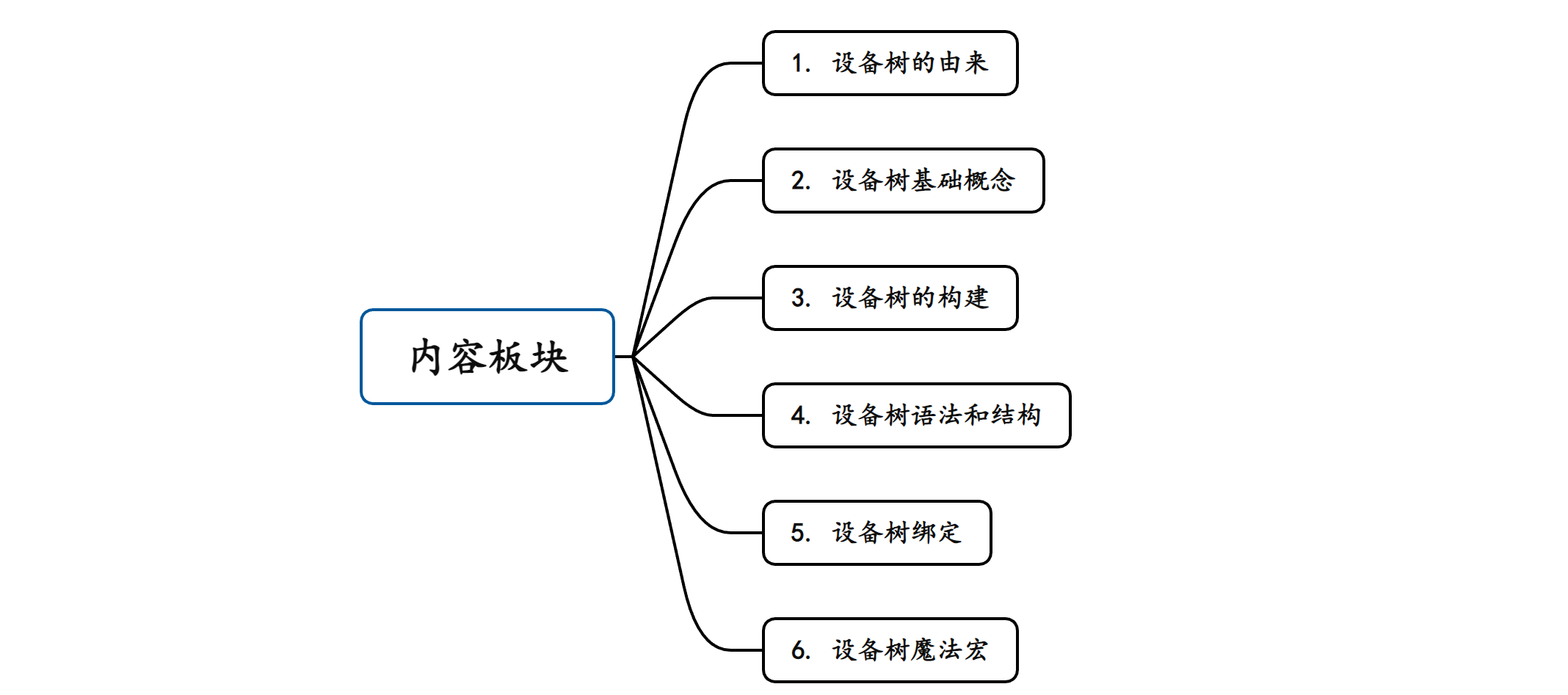

1. 设备树的由来
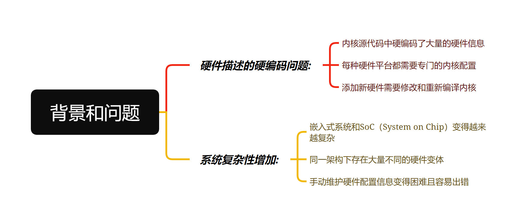
1.1 背景和问题
在设备树出现之前,操作系统内核面临以下挑战:
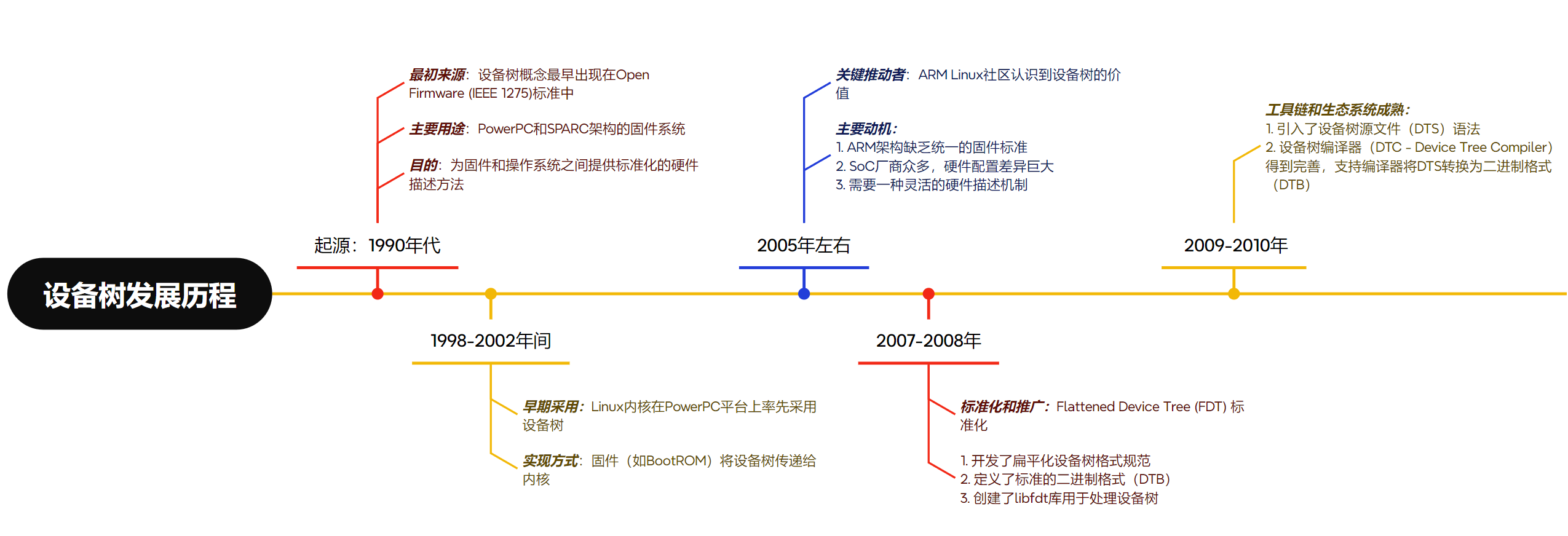
1.2 设备树发展历程
1.3 Linux 设备树的引入
在 Linux 内核 v2.6 版本以前,ARM 架构用于描述不同的硬件信息的文件都存放在 arch/arm/plat-xxx 和 arch/arm/mach-xxx 文件夹下,如下:
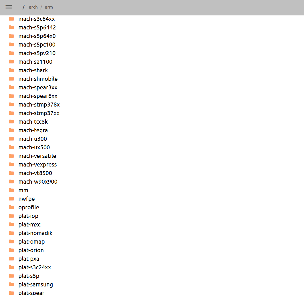
在这些文件内,都是通过手动定义不同的硬件设备,步骤非常繁琐:
// 每个机器文件都需要重复类似的代码
static struct platform_device *my_machine_devices[] __initdata = {
    &s3c_device_usb,
    &s3c_device_lcd,
    // ... 每个机器都要手动列出所有设备
};

static void __init my_machine_init(void)
{
    // 每个机器都要手动初始化
    platform_add_devices(my_machine_devices,
                        ARRAY_SIZE(my_machine_devices));
}
每增加一个硬件配置都需要修改内核源码, 不同机器间的代码重复度高,移植到新硬件平台需要大量代码修改,难以复用已有的硬件描述。
这样就导致了Linux内核代码中充斥着大量的垃圾代码,因为不同的板级他们的硬件信息都不相同,这些都是硬件特有的信息,对内核而言没有任何的意义,但是往往这部分代码特别的多,造成内核的冗余。这种手工定义硬件的方式正是设备树机制被引入的主要原因,它解决了代码重复、维护困难和可移植性差等问题。
2. 设备树基础概念
2.1 定义
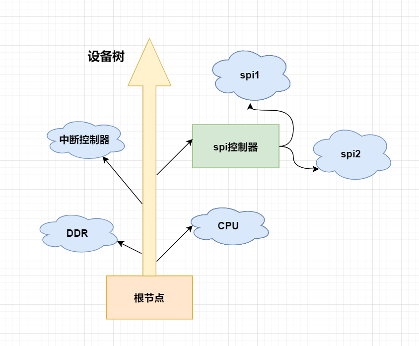
设备树(Device Tree) 是一种描述硬件的分层数据结构。
顾名思义,设备树就是一棵树,也称为 DTS(即设备树源)。
官方说明:
The “Open Firmware Device Tree”, or simply Device Tree (DT), is a data structure and language for describing hardware.
设备树是一种数据结构和一种用于描述硬件信息的语言。
Zephyr 使用 devicetree 来描述:
Zephyr RTOS 采用 DeviceTree 机制来描述硬件配置,这与现代 Linux 内核类似,但针对嵌入式实时系统的特殊需求进行了优化。
2.2 Zephyr设备树的类型
Zephyr 设备树文件类型:
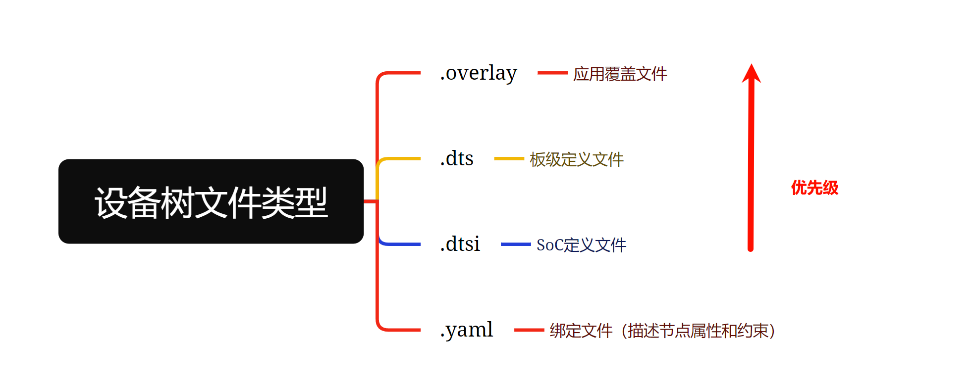
.overlay: 是 dts 的扩展文件
.dts : 每个支持的开发板都有一个来描述其硬件信息。包含一个或多个
.dtsi 文件用于描述 cpu 或者片上系统。
.yaml: 设备树绑定文件,允许构建系统时,生成可供设备驱动程序和应用程序使用的C宏的方式描述设备树源文件。
Zephyr 与 Linux 设备树的区别:
| 特性 | Zephyr | Linux |
|---|---|---|
| 处理时机 | 编译时处理设备树信息 | 运行时解析设备树 |
| 绑定格式 | 使用YAML格式定义绑定 | 使用文本格式定义绑定 |
| 结构特点 | 针对嵌入式系统进行简化和优化 | 适用于通用计算机系统 |
| 集成方式 | 与Zephyr构建系统深度集成 | 通过引导加载程序传递给内核 |
3. 设备树的构建
3.1 构建流程:
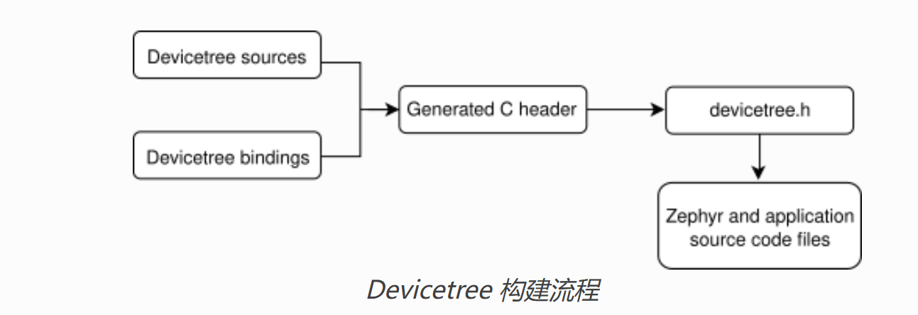

在 CMake 构建过程中,使用 C 预处理器处理将 .dts(包含.dtsi) 文件和 .overlay 文件合并为中间输出文件 zephyr.dts.pre 文件。
通过 scripts/dts/gen_defines.py 脚本处理预处理后的设备树和设备树绑定文件(.yaml),该脚本使用 Python 的 devicetree库(edtlib) 解析,并生成 C 宏定义,生成的宏定义保存在 devicetree.h 文件中。以及最终合并的设备树文件 build/zephyr/zephyr.dts。
驱动程序就通过包含 devicetree.h 提供的 API 来访问设备树信息:
#include <zephyr/devicetree.h>
3.2 脚本和工具
以下库和脚本位于 scripts/dts/ 中,它们根据输入文件创建输出文件。
dtlib.py: 低级 DTS 解析库。edtlib.py: 一个基于 dtlib 的库,它使用绑定来解释属性并提供设备树的更高级别视图。使用 dtlib 进行 DTS 解析。gen_defines.py: 使用 edtlib 从设备树和绑定生成 C 预处理器宏的脚本。
4. 设备树语法和结构
4.1 示例
以下是一个示例 DTS 文件:
/dts-v1/;

/ {
        a-node {
                subnode_nodelabel: a-sub-node {
                        foo = <3>;
                };
        };
};
节点
与任何树形数据结构一样,设备树也具有节点层次结构。上面的树有三个节点:
- 根节点:
/ - 根节点的子节点:
a-node a-node的子节点:a-sub-node
subnode_nodelabel:节点标签。 一个节点可以有零个、一个或多个节点标签。您可以使用节点标签来引用设备树中其他位置的节点。
foo:
foo是属性,是名称/值对。属性值可以是任意字节序列。在某些情况下,属性值是一个称为“单元”的数组。单元只是一个 32 位无符号整数。
节点a-sub-node具有一个名为foo的属性,是一个值为 3 的单元格。 foo 值的大小和类型由 DTS 中的尖括号”<” 和 “>”表示。
设备树路径:
由斜杠 / 分隔的字符串,根节点的路径为单个斜杠: / 。否则,每个节点的路径由节点祖先的名称与节点自身的名称连接而成,并以斜杠分隔。例如,a-sub-node 的完整路径为/a-node/a-sub-node。
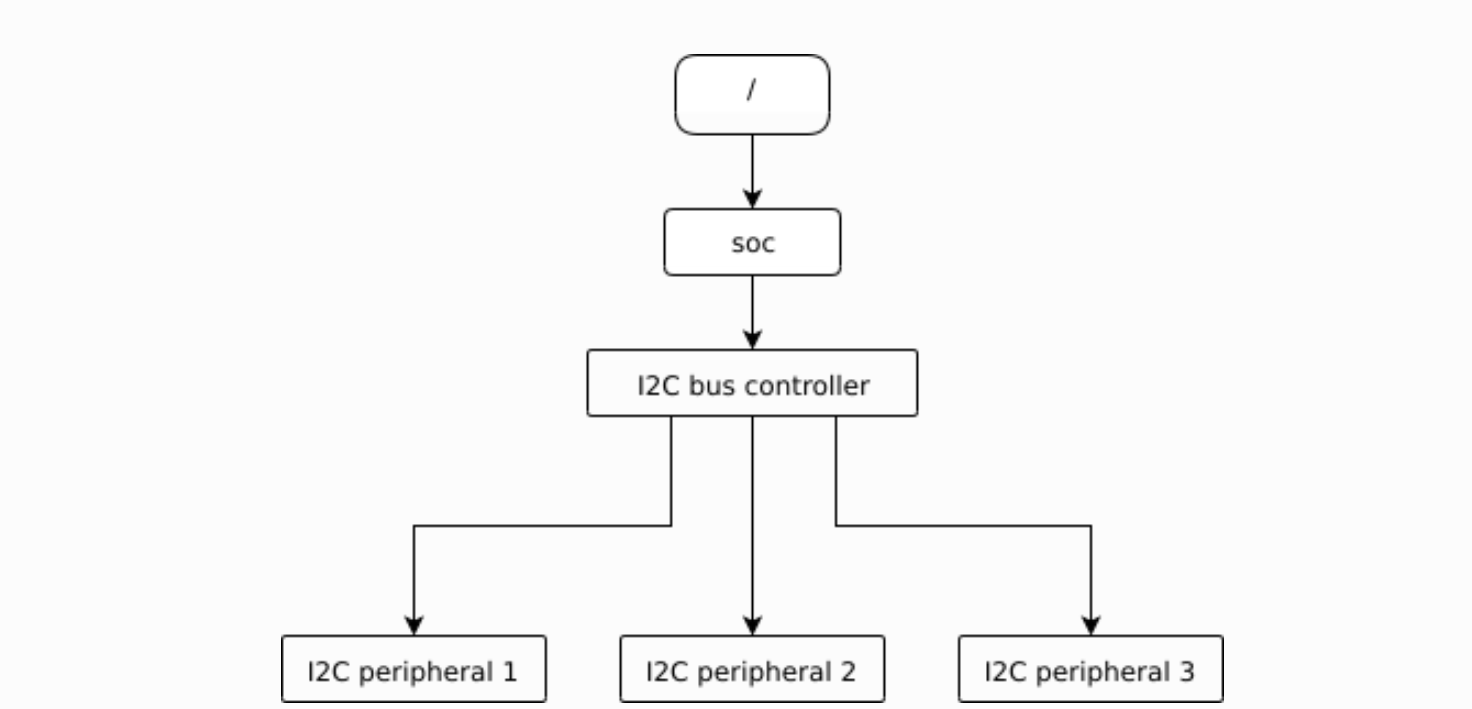
4.2 设备树与硬件的关系
设备树节点通常对应某些硬件,节点层次结构反映了硬件的物理布局。例如,假设一块开发板有三个 I2C 外设连接到 SoC 上的 I2C 总线控制器,如下所示:
/dts-v1/;

/ {
        soc {
                i2c-bus-controller {
                        i2c-peripheral-1 {
                        };
                        i2c-peripheral-2 {
                        };
                        i2c-peripheral-3 {
                        };
                };
        };
};
真实描述
/dts-v1/;

/ {
        soc {
                i2c@40003000 {
                        compatible = "nordic,nrf-twim";
                        reg = <0x40003000 0x1000>;

                        apds9960@39 {
                                compatible = "avago,apds9960";
                                reg = <0x39>;
                        };
                        ti_hdc@43 {
                                compatible = "ti,hdc", "ti,hdc1010";
                                reg = <0x43>;
                        };
                        mma8652fc@1d {
                                compatible = "nxp,fxos8700", "nxp,mma8652fc";
                                reg = <0x1d>;
                        };
                };
        };
};
单元地址:
@ 后的部分。单元地址给出了节点在其父节点地址空间中的地址。
例如,命名的节点 i2c@40003000表示一个 I2C 控制器,其寄存器映射基址为 0x40003000。
I2C外设地址:
外设在 I2C 总线上的地址。例如,apds9960@39 子节点在 I2C 控制器的地址为 0x39。
闪存分区:
这适用于使用设备树存储闪存分区表的情况。单元地址是分区在闪存中的起始偏移量。例如,以这个闪存设备及其分区为例:
flash@8000000 {
    /* ... */
    partitions {
            partition@0 { /* ... */ };
            partition@20000 {  /* ... */ };
            /* ... */
    };
};
名为 partition@0 的节点相对于其闪存设备起始位置的偏移量为 0,因此其基地址为 0x8000000。同样,名为 partition@20000 的节点的基地址为 0x8020000。
4.3 常见重要属性

compatible
节点所代表的硬件设备的名称。
推荐格式为"vendor,device",或者gpio-keys这种。
例如:
        apds9960@39 {
                compatible = "avago,apds9960";
                reg = <0x39>;
        };
avago:是供应商名称的缩写
apds9960:通常取自数据手册
compatible 属性可以写多个字符串,表示设备既属于某个具体型号,也属于某个通用系列。匹配驱动时,系统会优先用最具体的 compatible 值(比如型号),如果没有对应驱动,再用更通用的值(比如系列)。这样可以让同一个驱动支持多个型号,也能让特定型号用专用驱动。
举例:
compatible = "vendor,chip123", "vendor,chip-series";
系统会先找支持 “vendor,chip123” 的驱动,没有的话再找支持 “vendor,chip-series” 的驱动。
reg
指定设备的寄存器地址范围,它告诉操作系统内核设备使用了哪些物理地址空间。这包括寄存器的起始地址和长度。
reg 属性的格式通常如下:
reg = <address length>;  # 单个地址
reg = <address1 length1>, <address2 length2>;  # 多个地址
示例:
uart0: serial@101f1000 {
    compatible = "arm,pl011";
    reg = <0x101f1000 0x1000>;
    interrupts = <0 1 9>;
}
uart0: 节点标签 (Label),可以在设备树的其他位置通过\&label_name来引用此节点。0x101f1000是 UART 控制器寄存器的起始物理地址0x1000是寄存器区域的长度(4KB)
status
指示设备节点的运行状态
有以下几个常见值:
"okay"– 设备可以使用,操作系统应该启用它"disabled"– 设备当前被禁用,操作系统不应该启用它"reserved"– 设备被保留,供特定软件使用"fail"– 设备不可操作"fail-..."– 设备不可操作,附加了特定原因
interrupts
interrupts 属性用于描述设备的中断信息,告诉操作系统内核设备使用哪个中断号以及中断的触发方式
interrupts 属性定义了设备的中断配置信息,包括:
- 中断号(IRQ number)
- 中断类型(触发方式)
- 中断优先级(某些架构)
格式:
interrupts = <中断号 中断类型 中断优先级>;
中断类型常见值
IRQ_TYPE_LEVEL_HIGH– 高电平触发IRQ_TYPE_LEVEL_LOW– 低电平触发IRQ_TYPE_EDGE_RISING– 上升沿触发IRQ_TYPE_EDGE_FALLING– 下降沿触发IRQ_TYPE_EDGE_BOTH– 双边沿触发
4.4 特殊节点

Aliases
提供了一种为设备节点创建简短别名的方法,使得在引用设备节点时更加方便。
作用:
- 为长路径设备节点提供简短易记的别名
- 提高设备树的可读性和可维护性
- 简化引用特定设备节点的过程
示例:
    / {
        aliases {
            serial0 = &uart0;
            serial1 = &uart1;
            ethernet0 = &gem0;
        };

        soc {
            uart0: serial@101f1000 {
                compatible = "arm,pl011";
                reg = <0x101f1000 0x1000>;
            };

            uart1: serial@101f2000 {
                compatible = "arm,pl011";
                reg = <0x101f2000 0x1000>;
            };

            gem0: ethernet@10200000 {
                compatible = "cadence,gem";
                reg = <0x10200000 0x1000>;
            };
        };
    };
在这个示例中,我们可以通过serial0来引用uart0节点,通过ethernet0来引用gem0节点。
chosen
用于指定系统级的配置选项和首选项。
chosen节点在Zephyr中主要用于:
- 指定系统级设备,如控制台、shell等
- 配置系统参数
- 传递运行时配置信息给内核和驱动程序
举例:
chosen {
    zephyr,console = &uart0;           // 指定控制台输出设备
    zephyr,shell-console = &uart1;     // 指定shell控制台设备
};
在代码中使用chosen节点:
在Zephyr应用程序中,可以通过设备树API访问chosen节点指定的设备:
#include <zephyr/device.h>
#include <zephyr/devicetree.h>

// 获取chosen节点指定的控制台设备
const struct device *console_dev = DEVICE_DT_GET(DT_CHOSEN(zephyr_console));

// 检查设备是否就绪
if (device_is_ready(console_dev)) {
    printk("Console device is ready\n");
} else {
    printk("Console device is not ready\n");
}
5. 设备树绑定
YAML(YAML Ain’t Markup Language) 是一种人类可读的数据序列化标准,Zephyr使用YAML文件来定义设备树绑定(Device Tree Bindings)。这些绑定文件描述了设备树节点应该具有的属性和格式,用于验证设备树并为代码生成提供元数据。
设备树节点使用其兼容属性与绑定进行匹配,在配置阶段,构建系统时会尝试将设备树中的每个节点与绑定文件 (.yaml) 匹配。成功匹配后,构建系统会在验证节点内容和生成节点宏时使用绑定文件中的信息。
5.1 示例
以下时设备树节点的示例:
bar-device {
    compatible = "foo-company, bar-device";
    num-foos = <3>;
};
以下是与上面节点匹配的最小绑定文件:
compatible: "foo-company, bar-device"

properties:
    num-foos:
        type: int
        required: ture
5.2 构建系统如何处理 yaml
构建系统使用 yaml 来验证设备树节点并将设备树的内容转换为 devicetree_generated.h 头文件。
例如,构建系统将使用上述绑定来检查节点 num-foos 中是否存在所需属性 bar-device,以及其值 <3> 是否具有正确的类型。
然后,构建系统将为 bar-device 节点的 num-foos 属性生成一个宏,该宏将扩展为整型文字 3。此宏允许您使用 API 在 C 代码中获取属性的值.
再例如,以下节点会导致构建错误,因为它没有num-foos属性,并且该属性在绑定中被标记为必需:
bad-node {
     compatible = "foo-company,bar-device";
};
5.3 设备树绑定语法
典型的Zephyr设备树绑定YAML文件包含以下部分:
title: 详细描述的简洁标题 [可选]

description: |
   设备描述

# 您可以使用以下语法包含来自其他绑定的定义:
include: other.yaml

compatible: "厂商,设备名"

# 属性定义
properties:
  属性名:
    type: 数据类型
    required: 是否必需
    description: 属性描述
    # 其他约束条件

child-binding:
  description: 子节点描述
  properties:
    属性名:
      type: 数据类型
      required: 是否必需
      description: 属性描述
  # 其他子节点约束

# 如果节点描述的是总线硬件,例如 SoC 上的 SPI 总线控制器,请使用“bus:”来指明是哪一个,如下所示:
bus: spi

# 如果节点显示为总线上的设备,例如外部
# SPI 存储芯片,请使用“on-bus:”来指定总线类型,如下所示。
# 与“compatible”类似,此键也会影响节点匹配的方式
# 绑定。
on-bus: spi

foo-cells:
    # 此处为“foo”域的“说明符”单元名称;例如“foo”
    # 值为“gpio”、“pwm”和“dma”。更多信息请参见下文。
- Title:绑定设备的简短描述,通常是硬件型号。
-
Description:提供节点硬件的自由格式描述。
-
Compatible:用于将节点与此绑定匹配
-
Properties: 描述了与绑定匹配的节点所包含的属性
compatible: "manufacturer,serial"

properties:
  reg:
    type: array
    description: UART peripheral MMIO register space
    required: true
  current-speed:
    type: int
    description: current baud rate
    required: true
上面示例中兼容manufacturer,serial 的节点必须包含 array 类型的reg和 int 类型的current-speed属性。
属性条目采用以下语法编写:
<property name>:
  required: <true | false>
  type: <string | int | boolean | array | uint8-array | string-array |
         phandle | phandles | phandle-array | path | compound>
  deprecated: <true | false>   #标记属性是否已弃用
  default: <default>  # 指定属性的默认值,当设备树中未指定该属性时使用
  description: <description of the property>
  enum:         # 指定属性允许的枚举值列表
    - <item1>
    - <item2>
    ...
    - <itemN>
  const: <string | int | array | uint8-array | string-array>  # 指定属性必须具有的常量值
  specifier-space: <space-name>  # 指定属性使用的单元格空间名称
举例:
properties:
    # Describes a property like 'current-speed = <115200>;'. We pretend that
    # it's obligatory for the example node and set 'required: true'.
    current-speed:
        type: int
        required: true
        description: Initial baud rate for bar-device

    # Describes an optional property like 'keys = "foo", "bar";'
    keys:
        type: string-array
        description: Keys for bar-device

    # Describes an optional property like 'maximum-speed = "full-speed";'
    # the enum specifies known values that the string property may take
    maximum-speed:
        type: string
        description: Configures USB controllers to work up to a specific speed.
        enum:
           - "low-speed"
           - "full-speed"
           - "high-speed"
           - "super-speed"

    # Describes an optional property like 'resolution = <16>;'
    # the enum specifies known values that the int property may take
    resolution:
      type: int
      enum:
       - 8
       - 16
       - 24
       - 32

    # Describes a required property '#address-cells = <1>';  the const
    # specifies that the value for the property is expected to be the value 1
    "#address-cells":
        type: int
        required: true
        const: 1

    int-with-default:
        type: int
        default: 123
        description: Value for int register, default is power-up configuration.

    array-with-default:
        type: array
        default: [1, 2, 3] # Same as 'array-with-default = <1 2 3>'

    string-with-default:
        type: string
        default: "foo"

    string-array-with-default:
        type: string-array
        default: ["foo", "bar"] # Same as 'string-array-with-default = "foo", "bar"'

    uint8-array-with-default:
        type: uint8-array
        default: [0x12, 0x34] # Same as 'uint8-array-with-default = [12 34]'
属性的类型值:
| 类型 | 描述 | DTS 中的示例 |
|---|---|---|
| string | 恰好一个字符串 | status = "disabled"; |
| int | 恰好一个 32 位值(单元格) | current-speed = <115200>; |
| boolean | 存在时为真, 为假时不存在的标志 | hw-flow-control; |
| array | 零个或多个 32 位值(单元格) | offsets = <0x100 0x200 0x300>; |
| uint8-array | 零个或多个字节, 十六进制(Devicetree规范中的“bytestring”) | local-mac-address = [de ad be ef 12 34]; |
| string-array | 零个或多个字符串 | dma-names = "tx", "rx"; |
| phandle | 恰好一个 phandle | interrupt-parent = <&gic>; |
| phandles | 零个或多个 phandle | pinctrl-0 = <&uart2_tx_pd5 &uart2_rx_pd6>; |
| phandle-array | 一个 phandle 和 32 位单元的列表(通常是说明符) | dmas = <&dma0 2>, <&dma0 3>; |
| path | 作为 phandle 路径引用或路径字符串的节点路径 | zephyr,bt-c2h-uart = &uart0; 或者 foo = "/path/to/some/node"; |
| compound | 适用于更复杂类型的全部内容(不会生成宏) | foo = <&label>, [01 02]; |
- phandle:phandle(phandle pointer handle)表示对设备树中另一个节点的引用,类似于C语言中的指针。
示例:
        // 定义节点
gic: interrupt-controller@1000000 {
    compatible = "arm,cortex-a9-gic";
    interrupt-controller;
    #interrupt-cells = <3>;
};

uart0: serial@12340000 {
    compatible = "arm,pl011";
    reg = <0x12340000 0x1000>;
    interrupts = <0 1 0xf04>;
    interrupt-parent = <&gic>;  // phandle类型,引用gic节点
};
绑定文件定义:
properties:
    interrupt-parent:
        type: phandle
        description: 指定中断控制器节点
- phandles: phandles是phandle的复数形式,表示零个或多个节点引用的数组
示例:
pinctrl-0 = <&usart2_tx_pd5 &usart2_rx_pd6>;  // phandles类型,引用两个节点

// 更复杂的示例
pinctrl-0 = <&quadspi_clk_pe10 &quadspi_ncs_pe11
             &quadspi_bk1_io0_pe12 &quadspi_bk1_io1_pe13
             &quadspi_bk1_io2_pe14 &quadspi_bk1_io3_pe15>;
绑定文件定义:
properties:
    pinctrl-0:
        type: phandles
        description: 引脚控制配置节点引用列表
- phandle-array: 表示phandle和32位单元格(通常是说明符)的列表。
示例:
// GPIO配置示例
led {
    gpios = <&gpio0 17 GPIO_ACTIVE_HIGH>,  // gpio0的17号引脚,高电平有效
            <&gpio1 5 GPIO_ACTIVE_LOW>;    // gpio1的5号引脚,低电平有效
};

// DMA配置示例
device {
    dmas = <&dma0 2 1024>,     // dma0通道2,缓冲区大小1024
           <&dma0 3 512>;      // dma0通道3,缓冲区大小512
};
绑定文件定义:
properties:
 gpios:
    type: phandle-array
    description: GPIO配置数组
- path: path类型表示节点路径,可以是phandle路径引用或路径字符串。
示例:
// phandle路径引用
zephyr,bt-c2h-uart = &uart0;

// 字符串路径
some-path-property = "/soc/serial@12340000";
绑定文件定义:
    properties:
        zephyr,bt-c2h-uart:
            type: path
            description: 蓝牙控制UART设备路径
- compound: 用于更复杂的属性值,不会自动生成宏定义。
示例:
// compound类型示例
foo = <&label>, [01 02];
绑定文件定义:
properties:
  foo:
    type: compound
    description: 复合类型属性
- Child-binding:定义父节点可以拥有的子节点类型和属性。
-
Bus:如果节点是总线控制器, 要在绑定中说明总线类型。
例如,SoC 上 SPI 外设的绑定如下所示:
compatible: "manufacturer,spi-peripheral"
bus: spi
# ...
对于支持多种协议的单个总线,例如 I3C 和 I2C,bus 绑定中可以有一个列表作为值:
compatible: "manufacturer,i3c-controller"
bus: [i3c, i2c]
# ...
- On-bus:用于在YAML绑定文档中指定设备节点应该连接到哪种类型的总线。
举例:
父节点定义:
title: I2C Controller
description: |
  This binding describes an I2C controller node.

compatible:
  - "vendor,i2c-controller"

bus: i2c  # 声明这是一个I2C总线控制器

properties:
  "#address-cells":
    type: int
    const: 1

  "#size-cells":
    type: int
    const: 0

  reg:
    type: array

child-binding:
  # 子设备定义
子设备定义:
title: I2C Slave Device
description: |
  This binding describes an I2C slave device.

compatible:
  - "vendor,i2c-device"

on-bus: i2c  # 指定此设备应连接到I2C总线

properties:
  reg:
    type: int
    description: I2C device address
对应设备树:
i2c0: i2c@10010000 {
    compatible = "vendor,i2c-controller";
    #address-cells = <1>;
    #size-cells = <0>;
    reg = <0x10010000 0x1000>;

    temp_sensor@48 {
        compatible = "vendor,temp-sensor";
        reg = <0x48>;  // I2C地址
    };
};
- Specifier cell names (*-cells): 设备树中用于定义子节点地址和大小信息格式的属性。
主要包括:
#address-cells– 定义地址部分占用的单元数
#size-cells– 定义大小部分占用的单元数
#interrupt-cells– 定义中断描述符占用的单元数
举例:SPI总线设备
spi0: spi@10000000 {
    compatible = "vendor,spi-controller";
    #address-cells = <1>;
    #size-cells = <0>;
    reg = <0x10000000 0x1000>;

    spi-device@0 {
        compatible = "vendor,spi-device";
        reg = <0>;  // 片选号
        spi-max-frequency = <50000000>;
    };
};
yaml:
title: SPI Controller
description: |
  SPI controller with child device support.

compatible:
  - "vendor,spi-controller"

bus: spi

properties:
  "#address-cells":
    type: int
    const: 1

  "#size-cells":
    type: int
    const: 0

  reg:
    type: array

child-binding:
  title: SPI Device
  on-bus: spi

  properties:
    reg:
      type: int
      description: Chip select number

    spi-max-frequency:
      type: int
      description: Maximum SPI frequency

  required:
    - reg
- Include: 允许一个绑定文件引用或包含另一个绑定文件的内容。
单个包含
include: gpio-device.yaml
多个包含
include:
  - gpio-device.yaml
  - spi-device.yaml
举例:led-driver.yaml
# led-driver.yaml
include: gpio-device.yaml

# 定义LED特定的属性
properties:
  - name: label
    description: LED的标签名称
    type: string
    required: true
  - name: active-low
    description: 是否为低电平有效
    type: boolean
    default: false
6. 设备树魔法宏
在 Zephyr RTOS中,“Magic Macros”(魔法宏)是指那些自动生成的、用于访问设备树信息的C语言宏。这些宏极大地简化了设备树数据在C代码中的访问,使得开发者可以方便地获取设备树中定义的硬件配置信息。
6.1 给 Linux 开发人员的说明
熟悉设备树的 Linux 开发人员应该注意,这里描述的 API 与设备树在 Linux 上的使用方式有很大不同。
Linux 内核不会生成包含所有设备树数据的 C 头文件,然后将其抽象到宏 API 后面,而是会读取设备树数据结构的二进制形式。二进制表示形式在运行时进行解析,例如用于加载和初始化设备驱动程序。
Zephyr 不能以这种方式工作,因为设备树二进制文件和相关处理代码太大,无法适应 Zephyr 支持的相对受限的设备。
6.2 节点标识符
想要在程序中获取特定设备树节点的信息,您需要得到该节点的节点标识符。
相关 API 参考路径:include\zephyr\devicetree.h
获取节点标识符的主要方法如下:
| 方法 | 说明 | 示例 |
|---|---|---|
DT_PATH() |
指定设备树中节点的完整路径 | DT_PATH(leds, led_0) |
DT_NODELABEL() |
用于从节点标签获取节点标识符 | DT_NODELABEL(led_0) |
DT_ALIAS() |
用于获取特殊节点属性的节点标识符 | DT_ALIAS(led0) |
DT_INST() |
主要由设备驱动程序完成,因为实例编号是一种基于匹配的兼容节点来引用单个节点的方式 | DT_INST(0, gpio_leds) |
DT_CHOSEN() |
获取/chosen节点属性的节点标识符 | DT_CHOSEN(zephyr_console) |
DT_PARENT() and DT_CHILD() |
获取父节点或子节点的节点标识符 | DT_PARENT(node_id), DT_CHILD(node_id, child_name) |
示例:
/dts-v1/;

/ {

    aliases {
        sensor-controller = &i2c1;
    };

    soc {
        i2c1: i2c@40002000 {
            compatible = "vnd,soc-i2c";
            label = "I2C_1";
            reg = <0x40002000 0x1000>;
            status = "okay";
            clock-frequency = < 100000 >;
        };
    };
};
以下是获取i2c@40002000节点的节点标识符的几种方法:
DT_PATH(soc, i2c_40002000)-
DT_NODELABEL(i2c1) -
DT_ALIAS(sensor_controller) -
DT_INST(x, vnd_soc_i2c)x表示某个未知数。
设备树名称中的非字母数字字符(例如短划线 ( -) 和 @ 符号 ( @))将转换为下划线 ( _)。DTS 中的名称也会转换为小写。
节点表示符不是值,没有办法将其存储在变量中。你不能这样写:
/* These will give you compiler errors: */

void *i2c_0 = DT_INST(0, vnd_soc_i2c);
unsigned int i2c_1 = DT_INST(1, vnd_soc_i2c);
long my_i2c = DT_NODELABEL(i2c1);
如果您想要一些简短的内容来节省打字时间,请使用 C 宏:
/* Use something like this instead: */

#define MY_I2C DT_NODELABEL(i2c1)

#define INST(i) DT_INST(i, vnd_soc_i2c)
#define I2C_0 INST(0)
#define I2C_1 INST(1)
6.3 属性访问
6.3.1 检查属性和值
DT_NODE_HAS_PROP() 可以用来检查某个节点是否具有某个属性。
DT_NODE_HAS_PROP(DT_NODELABEL(i2c1), clock_frequency)  /* expands to 1 */
DT_NODE_HAS_PROP(DT_NODELABEL(i2c1), not_a_property)   /* expands to 0 */
6.3.2 读取属性值
DT_PROP(node_id, property)用于读取基本整数、布尔值、字符串、数字数组和字符串数组属性。
DT_PROP(DT_PATH(soc, i2c_40002000), clock_frequency)  /* This is 100000, */
DT_PROP(DT_NODELABEL(i2c1), clock_frequency)          /* and so is this, */
DT_PROP(DT_ALIAS(sensor_controller), clock_frequency) /* and this. */
以及常用的:
DT_CHOSEN,DT_HAS_CHOSEN:用于特殊/chosen节点的属性DT_HAS_COMPAT_STATUS_OKAY,DT_NODE_HAS_COMPAT:与compatible属性相关的全局和节点特定测试DT_BUS:获取节点的总线控制器(如果有)DT_ENUM_IDX:用于值在固定选择列表中的属性
--
6.4 实际驱动开发场景
让我们从一个具体的驱动开发场景来理解设备树的实际用途。
6.4.1 场景:开发一个可配置的GPIO LED驱动
假设我们正在为一个嵌入式系统开发LED驱动,需要支持以下可配置参数:
- LED连接的GPIO引脚和端口
- LED的默认状态(开/关)
- LED的亮灭逻辑(高电平点亮还是低电平点亮)
- LED闪烁频率
传统做法的问题:
如果没有设备树,我们需要在驱动源码中硬编码这些参数:
// 硬编码方式 - 不灵活
#define LED_GPIO_PORT    "GPIO_0"
#define LED_GPIO_PIN     17
#define LED_ACTIVE_HIGH  true
#define LED_DEFAULT_ON   false
#define LED_BLINK_FREQ   500  // ms
这种方式的问题是:每换一块板子或者改变LED连接方式,都需要重新编译驱动代码。
使用设备树解决:
第1步:在设备树中描述硬件配置
/ {
    leds {
        compatible = "gpio-leds";

        led0: led_0 {
            gpios = <&gpio0 17 GPIO_ACTIVE_HIGH>;
            label = "User LED";
            default-state = "off";
            blink-frequency = <500>;
        };

        led1: led_1 {
            gpios = <&gpio1 5 GPIO_ACTIVE_LOW>;
            label = "Status LED";
            default-state = "on";
            blink-frequency = <1000>;
        };
    };
};
第2步:创建设备树绑定文件 (gpio-leds.yaml)
compatible: "gpio-leds"

child-binding:
  description: GPIO LED configuration

  properties:
    gpios:
      type: phandle-array
      required: true
      description: GPIO pin configuration

    label:
      type: string
      description: Human readable string describing the LED

    default-state:
      type: string
      enum:
        - "on"
        - "off"
      default: "off"
      description: Initial state of the LED

    blink-frequency:
      type: int
      default: 1000
      description: Default blink frequency in milliseconds
第3步:在驱动中使用设备树信息
#include <zephyr/devicetree.h>
#include <zephyr/drivers/gpio.h>

#define DT_DRV_COMPAT gpio_leds

struct led_config {
    const struct device *gpio_dev;
    gpio_pin_t pin;
    gpio_flags_t flags;
    const char *label;
    bool default_on;
    uint32_t blink_freq;
};

struct led_data {
    bool current_state;
    struct k_timer blink_timer;
};

static int led_init(const struct device *dev)
{
    const struct led_config *config = dev->config;
    struct led_data *data = dev->data;

    // 检查GPIO设备是否就绪
    if (!device_is_ready(config->gpio_dev)) {
        printk("GPIO device %s not ready\n", config->gpio_dev->name);
        return -ENODEV;
    }

    // 配置GPIO引脚为输出
    int ret = gpio_pin_configure(config->gpio_dev, config->pin,
                                GPIO_OUTPUT | config->flags);
    if (ret < 0) {
        return ret;
    }

    // 根据设备树配置设置LED的初始状态
    data->current_state = config->default_on;
    if (config->default_on) {
        // 默认开启:根据GPIO_ACTIVE_LOW标志设置正确的电平
        gpio_pin_set(config->gpio_dev, config->pin,
                    (config->flags & GPIO_ACTIVE_LOW) ? 0 : 1);
    } else {
        // 默认关闭:根据GPIO_ACTIVE_LOW标志设置正确的电平
        gpio_pin_set(config->gpio_dev, config->pin,
                    (config->flags & GPIO_ACTIVE_LOW) ? 1 : 0);
    }

    printk("LED %s initialized on GPIO pin %d, default state: %s\n",
           config->label, config->pin, config->default_on ? "ON" : "OFF");

    return 0;
}

// 为每个LED实例创建设备
#define LED_DEVICE(node_id)                                          \
    static const struct led_config led_config_##node_id = {          \
        .gpio_dev = DEVICE_DT_GET(DT_GPIO_CTLR(node_id, gpios)),    \
        .pin = DT_GPIO_PIN(node_id, gpios),                         \
        .flags = DT_GPIO_FLAGS(node_id, gpios),                     \
        .label = DT_PROP_OR(node_id, label, "Unknown LED"),         \
        .default_on = DT_ENUM_IDX_OR(node_id, default_state, 0),    \
        .blink_freq = DT_PROP_OR(node_id, blink_frequency, 1000),   \
    };                                                               \
    static struct led_data led_data_##node_id;                      \
    DEVICE_DT_DEFINE(node_id, led_init, NULL,                      \
                     &led_data_##node_id, &led_config_##node_id,    \
                     POST_KERNEL, CONFIG_LED_INIT_PRIORITY, NULL);

// 为所有状态为okay的LED节点创建设备
DT_FOREACH_CHILD_STATUS_OKAY(DT_NODELABEL(leds), LED_DEVICE)
第4步:用户如何使用
方式一、调用驱动中提供的LED控制API:
// LED驱动API定义
struct led_driver_api {
    int (*led_on)(const struct device *dev);
    int (*led_off)(const struct device *dev);
    int (*led_toggle)(const struct device *dev);
    int (*led_set_brightness)(const struct device *dev, uint8_t brightness);
};

// LED控制函数实现
static int led_on(const struct device *dev)
{
    const struct led_config *config = dev->config;
    struct led_data *data = dev->data;

    data->current_state = true;
    return gpio_pin_set(config->gpio_dev, config->pin,
                       config->flags & GPIO_ACTIVE_LOW ? 0 : 1);
}

static int led_off(const struct device *dev)
{
    const struct led_config *config = dev->config;
    struct led_data *data = dev->data;

    data->current_state = false;
    return gpio_pin_set(config->gpio_dev, config->pin,
                       config->flags & GPIO_ACTIVE_LOW ? 1 : 0);
}

static int led_toggle(const struct device *dev)
{
    const struct led_config *config = dev->config;
    struct led_data *data = dev->data;

    data->current_state = !data->current_state;
    return gpio_pin_toggle(config->gpio_dev, config->pin);
}

static int led_set_brightness(const struct device *dev, uint8_t brightness)
{
    // 简单的PWM亮度控制示例(需要PWM支持)
    const struct led_config *config = dev->config;

    if (brightness == 0) {
        return led_off(dev);
    } else if (brightness == 255) {
        return led_on(dev);
    } else {
        // 这里可以添加PWM控制逻辑
        printk("Brightness control not implemented\n");
        return -ENOTSUP;
    }
}

// API结构体
static const struct led_driver_api led_api = {
    .led_on = led_on,
    .led_off = led_off,
    .led_toggle = led_toggle,
    .led_set_brightness = led_set_brightness,
};
方式二、直接使用设备树宏
#include <zephyr/kernel.h>
#include <zephyr/device.h>
#include <zephyr/devicetree.h>
#include <zephyr/drivers/gpio.h>

// 获取设备树中定义的LED设备
const struct device *led0 = DEVICE_DT_GET(DT_NODELABEL(led_0));
const struct device *led1 = DEVICE_DT_GET(DT_NODELABEL(led_1));

// 直接通过设备树宏获取GPIO配置
const struct device *gpio0_dev = DEVICE_DT_GET(DT_GPIO_CTLR(DT_NODELABEL(led_0), gpios));
const gpio_pin_t led0_pin = DT_GPIO_PIN(DT_NODELABEL(led_0), gpios);
const gpio_flags_t led0_flags = DT_GPIO_FLAGS(DT_NODELABEL(led_0), gpios);
6.4.2 这种方式的优势
- 配置与代码分离:硬件配置信息在设备树中,驱动代码保持通用性
- 无需重编译:更换板子时只需修改设备树文件,不需要重新编译驱动
- 支持多实例:自动支持多个LED,每个都有独立配置
- 编译时验证:设备树绑定文件确保配置参数的正确性
- 易于维护:硬件工程师可以直接修改设备树,无需懂驱动代码
6.4.3 实际开发流程总结
当我们需要让驱动参数可配置时,按以下步骤进行:
- 识别可配置参数:确定哪些参数需要根据不同硬件平台调整
- 设计设备树节点结构:定义节点名称、属性名称和属性类型
- 编写绑定文件:创建.yaml文件描述属性约束和默认值
- 修改驱动代码:使用设备树API获取配置参数
- 板级配置:在板级设备树文件中添加具体配置
这样,用户通过修改设备树而不是源码就可以改变驱动行为,大大提高了代码的复用性和可维护性。
zephyr官方文档:https://docs.zephyrproject.org/latest/build/dts/index.html#devicetree-guide
了解 Heiweilu的小世界 的更多信息
订阅后即可通过电子邮件收到最新文章。


